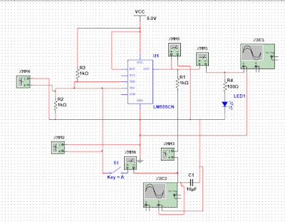
Thic circuit which has two states; ON and OFF state
Component Required- Wire
- Push Button
- Resistor
- Capacitor
- Voltage source
How the circuit works?
The 555 timer consists of two compactor and one SR latch and 8 dip pins.For this configuration we will be using 6 pins, except pin 4 and 7. See below in the figure for circuit configuration which I have simulated using Multisim.Initially, when the power is supplied to the circuit the voltage across the Threshold is greater than 2/3 of the Vcc thus it Resets the latch which is '0' logic. And when the push button is pressed then the trigger pin is grounded then the voltage falls below 1/3 of the Vcc the output form the pin 3 goes high as logic '1'. It is recommended to use the same value Resistor across Threshold pin and Trigger pin so the calculation becomes easy. This is how this circuit works.
. See the below figure for logicHowever, if the push button is never released the circuit oscillates ON and OFF with the frequency set by RC constant form the output pin 3.


No comments:
Post a Comment