1. Objective:
Design a Low Pass filter with the given gain of 4 and Pole of 1 kHz. And also to observe the output with the change in angular frequency.2. Schematics:

3. Theory:
A low pass filter is an electronic signal filter that filtrates all the unwanted high frequency signals. A designer can design this kind of circuit if they want only specific range of signals to pass through the circuit as shown in figure (1). In this kind of low pass filter with an Op Amp the Resistors controls the gain whereas the Capacitor controls the cutoff frequency. The right selection of resistor and capacitor gives the desired Gain and the cutoff frequency. The equations used for designing the Low Pass Filter are as follows
4. Equipment Used
- Breadboard
- 741 Op Amp
- DC power supply
- Wires
- Resistor and Capacitor
- LT Spice IV
4. Spice simulation result and plot


5. Measurements/Data/Analysis:
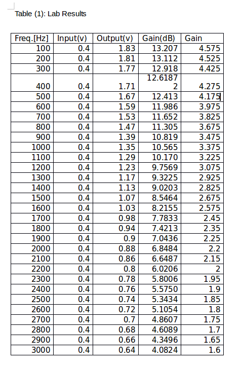

After the circuit was constructed on the lab, the above data in the table (1) was recorded. We measured the Vin with every increase in Frequency keeping the source Vin constant. The graph (1) was plotted gain v.s. frequency which was linear. The graph shows that the gain decreases as the frequency increases for the designed Low Pass Filter. However, the gain was over 10.56db until 1000 Hz frequency was reached in the lab. It meet out requirements as we designed our circuits to have a gain of 12 dB until 1 KHz frequency is reached. But, the theoretical gain was calculated to be 12.041 db. The gain was off by little because the measured Resistor and Capacitor were not 100% same as we used for the calculation for theoretical gain.
6. Discussion:
The results were verified which was gain of 12.041dB or 4 on simulation whereas 12.0599 dB and 4.03 on average until 1 KHz frequency was reached. The experimental errors couldn’t be avoided since the used passive components like the resistors and capacitor were not the same as we used for theoretical calculation. They were off by one tenth and 1 hundred of fraction. Overall, the lab was successful with a small percentage error which is less than 1%.
7. Conclusion
The designed low pass filter of gain 4 and pole 1 kHz was simulated using Lt Spice IV and constructed on breadboard with selected value of R1, R2 and calculated value for Capacitor from the given pole. Moreover, from this lab I learned to design a Low Pass Filter using an OP Amp for the desired gain and cutoff frequency or Pole.8. Hand calculation for components:

Easy now
ReplyDeleteglad it helped you someway :)
ReplyDeleteHow did you pick your Resistor and Capacitor?
ReplyDeleteto pick a resistor you need to know you Gain value. After it is determined then use equation I . To solve for the resistor value you may pick one of the resistor value and solve for the other.
DeleteWhereas to pick capacitor value you need to know your cutoff frequency for the filter. Here in this case its 1kHz i.e omega(w). So plug in the value of calculated value of R2 in equation III and solve for Cap. you may not find capacitor as calculated for your circuit if you want to implement on breadboard. However, it would be easier if you pick you Capacitor first and solve for the resistors.
Goodluck!
Nice. Thank you for providing such detailed information. I was looking for a low pass filter a few months ago and tried to buy it online in numerous locations. However, the cost is expensive in a few local regions, So I started searching the internet for the best website for low pass filters. Finally, I identified Anatech Electronics to be the best website. I was able to obtain all of the products at the most competitive prices. Anatech Electronics provided me with all of the necessary low pass filters, as well as the custom low pass filter designs that I requested. Finally, I received all of the products on time in excellent condition. This is the place to go if you're looking for a low pass filter. You may get a high-quality low pass filter from them.
ReplyDelete